
Flush-through cleaning
Useful when a compatible cleaning fluid can reach all wetted surfaces at the required flow and contact conditions. The supply, return and disposal route must be defined.
Liquid filling machinery guidance
A filling machine is only as changeable as its least accessible product-contact point. Define the products, cleaning method, dismantling limits and verification evidence before choosing the pump, hoses, valves and nozzles.
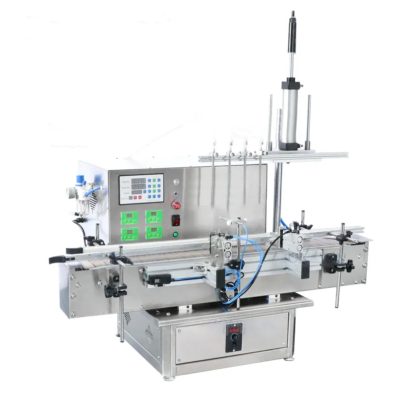
Cleaning is a specification input
The cleaning objective should be measurable and relevant to the product risk.
“Easy to clean” is not a single machine property. The required design depends on what must be removed, whether the next product is compatible, whether an allergen or colour change is involved, which cleaning agents are permitted and how cleanliness will be confirmed. The same filler may need a short flush for one compatible product family and a controlled dismantling procedure for another.
Map every surface that the liquid can touch from the supply vessel to the nozzle tip. Include temporary hoses, recirculation branches, seals, valve cavities, manifolds, drip trays and any recovery route. A product path that is overlooked during specification can become the longest part of the changeover.
Map the wet side
Treat temporary hoses and operator-fitted parts as part of the machine, not as an afterthought.
| Product-path area | Questions to resolve | Evidence to request |
|---|---|---|
| Source vessel or IBC connection | How is the connection drained, isolated and protected between batches? | Connection drawing, hose specification and cleaning sequence. |
| Feed hose or pipework | Can it be flushed, removed, inspected and dried where required? Are low points created by the installation? | Route drawing, hose length, connection type and drainage check. |
| Pump or metering element | Which internal surfaces, seals or tubes contact product and what must be dismantled? | Exploded view, product-contact list and approved cleaning method. |
| Valves and manifolds | Are there trapped volumes, blind branches or product-return paths? | Flow diagram and inspection points. |
| Filling nozzles | Can the shut-off tip, seals and anti-drip parts be accessed without losing settings? | Nozzle strip-down demonstration and parts list. |
| Drains, recovery and waste | Where does rinse liquid or displaced product go and how is cross-connection prevented? | Drain plan, recovery method and operator procedure. |
Choose a cleaning strategy
Cleaning method affects pump selection, valve design, hose routing and operator time.
Useful when a compatible cleaning fluid can reach all wetted surfaces at the required flow and contact conditions. The supply, return and disposal route must be defined.
Appropriate where components need visual inspection or separate cleaning. Check tool access, part handling, reassembly controls and the risk of damage or incorrect fitting.
Peristaltic tubing or other replaceable contact parts can reduce retained product and cross-contact, but tubing specification, disposal, priming and repeatable installation still need control.
A dedicated hose, pump head or nozzle set can reduce changeover risk for incompatible products. Storage, identification and connection error prevention become part of the process.
Build the changeover sequence
A timed changeover trial should include safe isolation, cleaning, reassembly, priming and approval—not only the mechanical adjustment.
| Stage | Control point | What to record |
|---|---|---|
| End the current batch | Recover or dispose of remaining product safely and identify what remains in the line. | Last pack, product balance and disposition. |
| Make safe | Stop movement, isolate energy and control pressure or hazardous product before intervention. | Isolation step and authorised operator. |
| Drain and dismantle | Use a defined order so removed parts are contained, identified and protected. | Parts removed and condition found. |
| Clean and inspect | Apply the approved method and inspect the areas that can retain residue. | Cleaning cycle, agent, temperature where relevant and inspection result. |
| Reassemble and line-clear | Fit the correct seals, hoses, nozzles and guards; remove tools and previous-product labels. | Independent check where required. |
| Prime and verify | Prime with the next product or approved medium, reject transition packs and confirm fill performance. | Recipe, rejects, first approved pack and quantity checks. |
Verification evidence
The acceptance method should be agreed before the machine is built or modified.
Use inspection points and a documented strip-down sequence where visual assessment is part of release. A surface that cannot be reached or inspected may need a different design or validation method.
Record the cleaning agent, concentration, contact condition, flow route and rinse endpoint where these are controlled process variables. Avoid assuming that a longer rinse automatically reaches trapped areas.
After reassembly, confirm correct parts, leak-free operation, stable priming, quantity control and nozzle shut-off before releasing production packs.
Cleaning and changeover questions
General guidance must be converted into a site-approved cleaning procedure.
That depends on product risk, product-path geometry, available cleaning services and the verification method. Many systems use a combination: flushing for the main path and controlled removal of selected parts.
It can keep the liquid inside replaceable tubing, which may simplify the contact path. The nozzle, connectors, external spill areas and installation procedure still require control, and the correct tubing must be confirmed for the product.
Use the transition that is most difficult to clean or detect, not only two similar products. Consider strong colours, fragrances, allergens, reactive residues and products that dry or cure.
Define the same start and finish points for each option. Include safe shutdown, draining, cleaning, inspection, reassembly, priming, checks and release of the first acceptable packs.
Yes. Product compatibility and cleaning-agent compatibility both matter. Confirm concentration, temperature, exposure time and seals as well as the main metallic or polymeric parts.
Authoritative hygienic-design context
The European Hygienic Engineering & Design Group hygienic design principles explain why equipment intended for food manufacture should be designed around cleanability and contamination prevention. Applicability and validation depend on the product, process and site risk assessment.
Continue the specification
Prepare a useful enquiry
Send the product family, proposed cleaning method, changeover sequence and any residue or cross-contact constraints so Lancing can review the wet-side arrangement.