
Rate capability
Each machine needs sufficient capability at the actual product and pack, but unlimited overspeed is not a substitute for stable control.
Liquid filling machinery guidance
A fast filler cannot deliver a reliable line if containers arrive irregularly, closures are unavailable, labels reject good packs or every downstream stop empties the nozzles. Define the complete process and control boundaries.
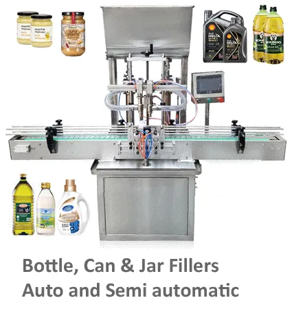
Map the pack and information flow
Integration begins with a process map, not with joining conveyor frames.
List every operation from empty-container supply to the point at which a good finished pack leaves the scope. Include orienting, rinsing, filling, closure presentation, capping, sealing, coding, inspection, labelling, reject handling, accumulation and case packing where applicable. For each step, define the pack state, required spacing and what happens when the next step is unavailable.
The control architecture should define which machine owns the line start, stop and speed reference; how ready, run, fault and blocked conditions are exchanged; and how packs already inside the line are handled after a stop. Mechanical interfaces, electrical signals and operating procedures should be reviewed together.
Interface matrix
Interfaces should be testable, not implied.
| Interface | Questions to answer | Evidence |
|---|---|---|
| Empty-container infeed | What pitch, orientation, queue pressure and minimum buffer are required? | Pack samples, infeed rate and low-container response. |
| Product feed | Who controls transfer, pressure, level, mixing, temperature and low-product stop? | Flow diagram, signals and refill sequence. |
| Filler to capper | How are wet necks, product slosh, spacing and uncapped accumulation controlled? | Filled-pack transfer test and stop/restart sequence. |
| Closure supply | How are low caps, jams, misorientation and replenishment communicated? | Alarm matrix and controlled run-down behaviour. |
| Labeller/coder/inspection | What product presence, speed and reject signals are exchanged? | Good/bad pack tests and reject confirmation. |
| Accumulation | Where can packs safely queue, and which packs must not accumulate? | Capacity calculation and blocked/downstream stop test. |
| Line controls | Which system owns start, stop, reset, speed and recipe selection? | Signal list, cause-and-effect and HMI responsibility. |
| Utilities and safety | How are isolation, emergency stops, guarding and site systems coordinated? | Approved layout, risk assessment and site test plan. |
Balance the line
The best buffer location depends on the failure modes and pack condition.
Each machine needs sufficient capability at the actual product and pack, but unlimited overspeed is not a substitute for stable control.
Define how each machine slows or stops when upstream supply is low or downstream is unavailable. Avoid rapid repeated cycling that creates product or pack defects.
Place accumulation where it protects useful output and product quality. Uncapped, foaming, unstable or temperature-sensitive packs may have strict limits.
Caps, labels, coding consumables and product refill create real interruptions. Include walking, lifting and safe access in the operating study.
Identify where a bad pack is detected, how it is tracked, where it is rejected and how reject confirmation is handled.
Recipes, guides, change parts, labels, codes and inspection settings must move together. Independent line clearance may be required.
Plan controlled stops and restarts
Recovery tests should be agreed for FAT and repeated at SAT where site interfaces are involved.
| Scenario | Required decision | Acceptance check |
|---|---|---|
| Downstream stop | Complete current fills, pause before fill, or stop immediately? | No uncontrolled spill, double fill or unsafe queue. |
| Upstream starvation | Run existing packs out or hold position? | Correct pack tracking and no empty cycle where prohibited. |
| Emergency stop | What energy is removed and what product/pack state remains? | Safe state, clear reset conditions and no automatic unexpected restart. |
| Power or air loss | How are valves, nozzles, conveyors and retained packs left? | Fail state and recovery procedure demonstrated. |
| Rejected pack | Can the rejected item be removed without losing sequence? | Detection, tracking, physical reject and confirmation tested. |
| Recipe change | How are all linked machines confirmed on the correct format? | Line clearance and recipe/part verification completed. |
Integration questions
A responsibility matrix prevents gaps between machine suppliers and site services.
It depends on the frequency and duration of normal stops, pack stability, product quality limits and the value of keeping upstream equipment running. Use real interruption data where available.
A central control can simplify coordination, while linked stand-alone machines can also work when signals and responsibilities are well defined. The project architecture should match scope, service and validation needs.
Count good finished packs at the agreed line endpoint over a defined operating period, recording planned stops, faults, rejects and replenishment.
The answer depends on whether uncapped packs can safely accumulate and how long. The line should have a defined stop position and controlled recovery sequence.
The scope should name the supplier for each mechanical, electrical, pneumatic and software boundary, including signal testing and final documentation.
Continue the specification
Prepare a useful enquiry
Send the process sequence, pack formats, target good output, existing equipment, available footprint and control boundaries so Lancing can review a joined-up line concept.