
1. Product is presented to the meter
The source vessel, hopper, pipework or pump arrangement must keep the metering device supplied without pulling air, starving the inlet or allowing solids to settle away from the pickup.
Liquid filling machine fundamentals
A liquid filling machine moves product from a controlled supply through a metering system and nozzle into a correctly positioned container. The control system coordinates product flow, container presence and the end of the dose. The practical result depends not only on the pump or meter, but also on the product feed, nozzle shut-off, container handling and the conditions used to verify each fill.
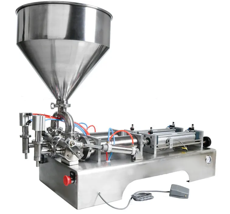
The filling sequence
Each stage can become the limiting factor when product behaviour or pack geometry changes.
The source vessel, hopper, pipework or pump arrangement must keep the metering device supplied without pulling air, starving the inlet or allowing solids to settle away from the pickup.
A piston, peristaltic pump, gear pump, load cell, flow meter or level-based system controls a defined quantity or endpoint. The suitable principle depends on what must be controlled and how the liquid behaves.
On an automatic line, sensors and stops confirm that a container is in the filling position. A semi-automatic system may rely on an operator, fixture or foot-switch sequence instead.
The nozzle controls where the liquid enters and how flow stops. Its diameter, tip geometry, shut-off and movement can affect foam, splash, strings, drips and neck cleanliness.
Valves close, pump motion stops or the target signal is reached. The machine then releases the container, advances the next pack and checks that the conditions for another fill are present.
The filled quantity and pack condition are sampled against an agreed method. Settings are meaningful only when the product temperature, source level, container and sequence are recorded with the result.
Technology differences
A product trial should confirm that the selected principle remains stable across the intended operating range.
| Filling principle | What controls the fill | Questions to resolve |
|---|---|---|
| Volumetric piston | A defined displaced volume | Can valves pass the product, and does product behaviour remain suitable at the selected stroke and speed? |
| Peristaltic pump | Calibrated tube displacement over controlled pump movement | Is the tubing chemically and mechanically suitable, and can it be primed without trapped air? |
| Gear or positive-displacement pump | Controlled pump rotation or run profile | Does the product lubricate and feed the pump correctly, and can flow stop cleanly? |
| Fill by weight | Measured net mass on a load cell | Can the container remain stable and isolated from external forces during measurement? |
| Fill to level | A physical liquid-level endpoint in the container | Is a common visual level the objective, and are container volume variations acceptable? |
Clear answers
The answer depends on the product, pack and operating conditions, so the relevant variables should be recorded rather than assumed.
The metering system controls the variable used to end the dose: displaced volume, pump movement, measured mass, measured flow or liquid level. It does not automatically control every part of pack quality. Nozzle behaviour, product aeration, container position and the product supply can still change the finished result even when the metering command is repeatable.
An automatic liquid filling machine normally uses a sensor, stop, gate or indexing mechanism to confirm container presence and position before filling is enabled. The sensing method must suit the real container material, colour, shape and spacing. The sequence should also define what happens when a container is missing, doubled, leaning or not fully located.
The same pump can behave differently because viscosity, density, temperature, foaming, dissolved air, particles and lubricity change how the liquid enters, moves through and leaves the product path. A pump that is stable with water may need a different speed profile, hose, valve, nozzle or feed arrangement for another product.
Between fills, the system must stop product cleanly, prevent unwanted draining or siphoning, release or advance the container and restore the conditions needed for the next dose. This reset period is where drips, pressure relaxation, trapped air and product-level changes often become visible, so it should be included in trials rather than judging only a single isolated fill.
The product-contact path may include the source vessel, pickup, hoses, manifolds, pumps, cylinders, valves, seals and nozzles. The exact path depends on the machine configuration. A buyer should ask for the proposed flow path and identify cleaning, compatibility and cross-contamination requirements before treating a general machine description as a confirmed specification.
Continue your specification
Use the next guide that matches the unresolved part of the application.
Compare the established machine families and their selection variables.
Review the supply conditions that keep the metering system full and stable.
Understand how the final part of the product path controls splash, foam and shut-off.
Send the product, container, target quantity and production context so the filling method and trial scope can be reviewed.